Everyone knows that any electronic device can be connected to a computer using a standard USB cable. Thus, using a laptop or personal computer, you can communicate with each other various devices such as printers, cameras, smartphones and data storage devices (flash drives and external hard drives).
What is OTG?
Is there a way to do without a computer? Quite simply, a lot of adapters under the general name OTG cable have appeared on the market for a long time. Their cost varies from a few dollars to a dozen or even two. However, their difference from simple data cables is so insignificant that you can easily make an OTG cable yourself. For example, from the remnants of old connectors, cables and adapters.
So, first we need to decide what we need an OTG cable for. Powering another device from the battery may be needed in the absence of power outlets nearby, for example, on trips or hiking trips, but this option is not the most efficient. We need to immediately decide whether we will connect two specific devices but constantly with each other, or is it better to make a universal OTG cable with your own hands for using any USB devices, like a store one. It's also best to check right away if your device is capable of supporting such connections.
Tools and safety technology
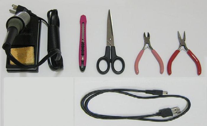
When working with cables, you will need:
insulation stripper;
nippers or side cutters (remember the saying: "measure 7 times - cut 1"), an extra solder on the cable will worsen the quality of communication between devices and increase the resistance in general, which will affect the loss of data or the impossibility of charging due to the resistance of the conductor;
soldering iron, solder and flux; at the end of the article we will look at how you can do without this device.
 Remember the safety measures when working with a soldering iron. This device is dangerous due to its high temperature not only during operation, but also for several minutes after switching off. Protect the work surface of the table from the ingress of molten tin or rosin. Protect exposed skin from touching hot parts of the soldering iron.
What is what?
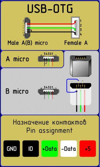
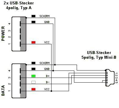
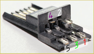
To begin with, it is worth making out which contacts in plugs and sockets are needed for what, since in the mini and micro versions there is 1 pin more than in the connectors of the universal serial bus... So, the first pin is standardly marked with red insulation inside the wire, designed to supply voltage. The second and third pins, marked with white and green insulation, are for data transmission. The fourth black pin is zero or ground, paired with the first supply wire. In mini- and micro-USB, such functions are assigned to the fifth, last pin, and the fourth is a marking or identifier. It is designed to feed connection information to the device and is not connected anywhere in the data cables at all.
The simplest option
First of all, consider the option of connecting two specific devices to each other, for example tablet computer and a camera. Since both of them have 5-pin sockets, be it micro or mini USB, you just need to carefully solder the corresponding wires together. 2 unnecessary data cables with matching plugs will do. You need to cut them and strip the wires from the insulation, and then connect them according to color differentiation, that is, black with black, yellow with yellow, and so on. Each connection must be isolated from the others with hot melt glue or at least electrical tape. When such a cable is connected to the devices, a dialog menu will appear on the screens, where you will need to select which of the devices will be the main one in this mini-network. You can forcibly designate the main and secondary devices in the cable itself. To do this, in the plug of the main device, you need to connect the 4th and 5th contacts, and in the other plug, simply do not connect the 4th contact to any one. Thus, the device will automatically determine itself as the master in the connection, since the marker contact will indicate the presence of a connection, while on the second device it will be "empty".
For a variety of devices
Consider the option of how to make a universal OTG cable with your own hands. In addition to the micro- or mini-USB plug, depending on the device, we need a USB connector. You can take it from the old motherboards, cut off from the USB extension cable or disassemble the USB hub (the so-called YUSB hub). The latter option is preferable, since it will allow you to connect several peripherals to the main device at once, like to a computer. The connection sequence is the same as above, the main device is forcedly indicated on the device plug in the same way, connecting the 4th and 5th pins. The figures clearly show the connection diagram of the pins in the connectors and plugs.
Connected to power supply
Some devices are characterized by increased power consumption, which leads to fast discharge the battery of the main gadget, be it a smartphone or tablet. In this case, the do-it-yourself OTG cable can be improved by adding a power cable with a USB plug for the power adapter. To do this, you can use the remnants of the data cable from which the micro or mini USB plug was previously cut off. The connection is made on two current-carrying contacts, black and red, ignoring the data wires. It should be remembered that over long distances the resistance of the wire reinforced with solder joints will reduce the voltage and amperage, so using long cable lengths will most likely not allow you to achieve a stable connection between the devices. Use approximately 20-30 cm of cable for each plug and connector to avoid breaks and interruptions in the connection.
Finally, I would like to mention how to assemble an OTG cable with your own hands without a soldering iron. The assembly principle is the same as described above, however, the wire connections are made in slightly different ways. Here are two of them:
Solder paste contains solder powder and flux and does not require a soldering iron. Such a paste is applied to the parts to be joined and heated with an ordinary lighter.
There are compounds without the use of high temperatures at all. The so-called adhesive tape locks are connectors for low-current systems with a special contact that cuts into the wires using a clamping device, for example, pliers.
Whatever you decide to do with your own hands, remember that cutting the cables is not a warranty case and such cables cannot be replaced.
If you have a smartphone or tablet based on operating system Android, then you might want to use it as a host for some kind of radio amateur electronics, such as an Arduino board.
This requires more than just a USB cable, but an On-The-Go (OTG) USB. You can buy one at a radio store or order online, but if you are too lazy to go shopping or do not want to wait for a parcel, you can make such a USB OTG cable with your own hands, since it is quite simple.
First, you will need two USB cables as donors. One of them must be type A with female connector and the other micro type B with male connector. When you're done, you will have a cable that connects to your phone on one side and a standard USB cable on the other side.
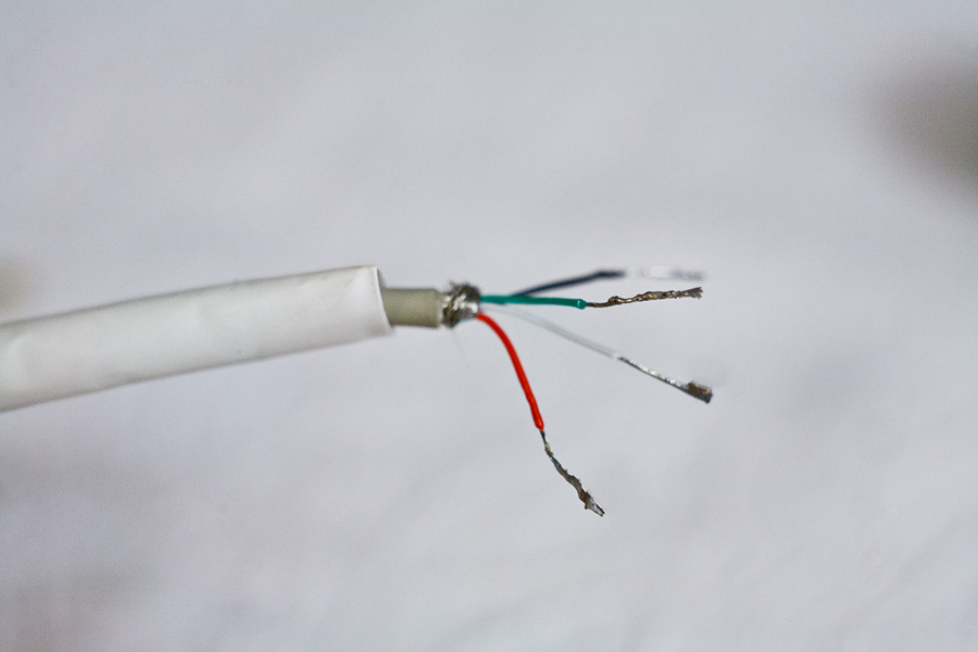
But first, cut these two donor cables so that you expose the red, black, white, and green wires running inside these cables. Strip the insulation off the ends of these wires. Color-match the wires of one cable and the other and solder them to each other. Insulate the soldered joints from each other using heat shrink tubing, electrical tape, or hot glue. Be sure to cover them with a sheath, which is a bare, stranded wire that surrounds the four colored wires.
After you've soldered the two cables together, wrap the connection with electrical tape for electrical and strain relief. Since many Android phones are USB OTG devices, that is, they can act as USB host or a slave, then you still need your phone in this case to act only as a host. You can verify this with a special sensitive pin in micro connector B. When this pin is connected to ground, USB device The OTG connected to the cable goes into host mode. If the pin remains in its normal disconnected state, the USB OTG device will remain in slave mode.
Now carefully open the micro B connector cover and solder pins 4 and 5 together. Once this is done, reassemble the micro B connector by placing a cover on it and securing it with electrical tape or glue to secure it.
To make sure everything works as it should, test your homemade cable by connecting one end to your phone or tablet on Android base and the other to the Arduino. If everything is installed correctly, then the Arduino should turn on as it will be powered. If this does not happen, then disconnect both ends of the cable and check it for a short circuit or an open. Keep in mind that you will not be able to test the data transfer capability until you write the appropriate programs for your phone and Arduino.
I talked about choosing a tablet, and in particular about such a necessary function for me as the ability to connect various USB devices to it, such as: flash drives, a card reader (and, accordingly, memory cards of different formats) and so on.
So, having bought a MoveO tablet! TPC-7HG I suddenly encountered a problem completely unexpected for me. The thing is that this tablet has only a mini-USB connector. In itself, this was not a surprise or a problem for me - on the contrary, it is easier to find a standard mini-USB cable to replace, for example, a broken charging cable on occasion. An unpleasant surprise for me was that in my town nowhere - ANYWHERE! - mini-USB OTG cable was not sold! It also did not come with the kit. Going to all possible and impossible stores, I came to the conclusion that, perhaps, it would be easier and faster to make such a cable with your own hands.
ATTENTION!!! EVERYTHING YOU DO - YOU DO AT YOUR OWN RISK !!!
And now a little theory. You cannot simply take and solder together a mini-USB plug with a piece of wire from one cable and the so-called USB-female plug from another cable. No, that is, of course, you can solder something, but just connect to the tablet and make it work with this cable not a single device will work. Here's the thing.
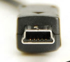
The standard mini-USB cable has a five-pin plug:
001.
Contacts in it are numbered as follows:
002.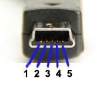
But there are only 4 wires in a standard USB cable. Where did the fifth wire go? Yes, nowhere. It simply does not solder to the end switches of the connector!
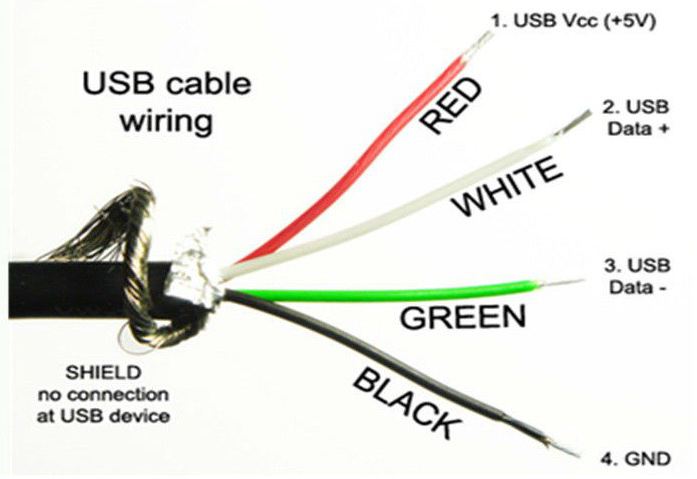
Appointment and color coding the wires in a regular USB cable are as follows:
1 - Red VBUS (+ 5V) +5 Volts DC voltage relative to GND. The maximum current is 500 mA.
2 - White D- (-Data)
3 - Green D + (+ Data)
4 - Black GND - common wire, "ground", "minus", 0 Volts
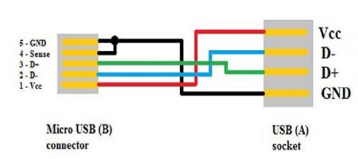
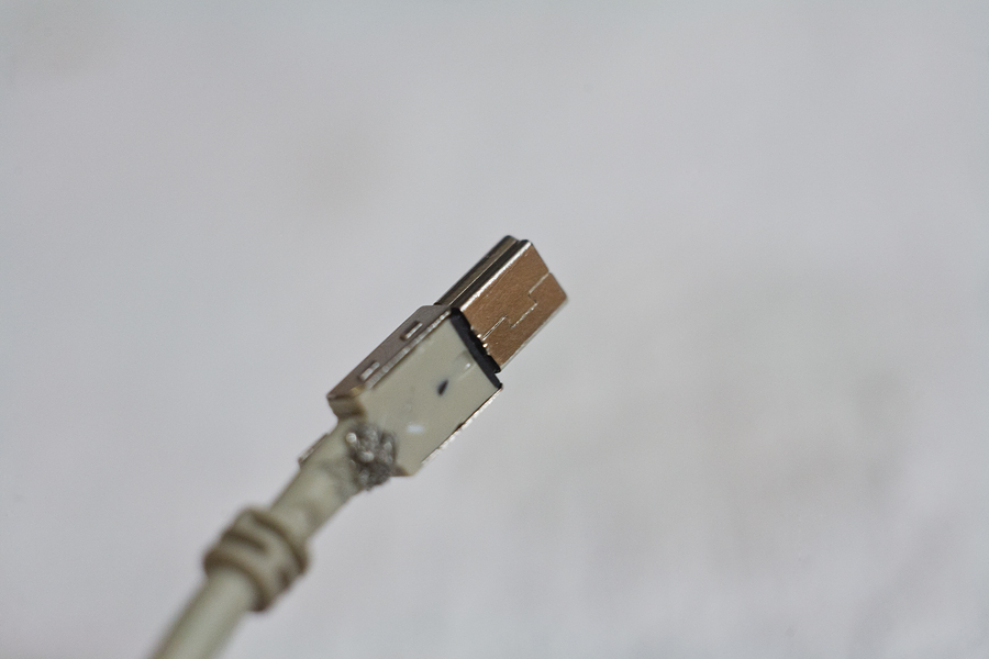
The main thing contrast usb OTG cable consists of a plug. In a mini-USB OTG cable (however, as well as in micro-USB OTG cable) pins 4 and 5 are shorted to each other. In a regular (not OTG) data cable, a wire is not soldered to the 4th pin of the plug. This plug is called USB-BM mini (micro). If you solder pins 4 and 5 together, then such a plug will be called USB-AM mini (micro). It is by the presence of a jumper between 4 and 5 contacts in the USB-AM micro plug that the tablet determines what is going to be connected to it. peripheral device... If this jumper is not present, then it will act as a passive device itself and will not react to any kind of USB devices connected to it.
So, we got acquainted with the theory - let's get down to practice.
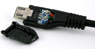
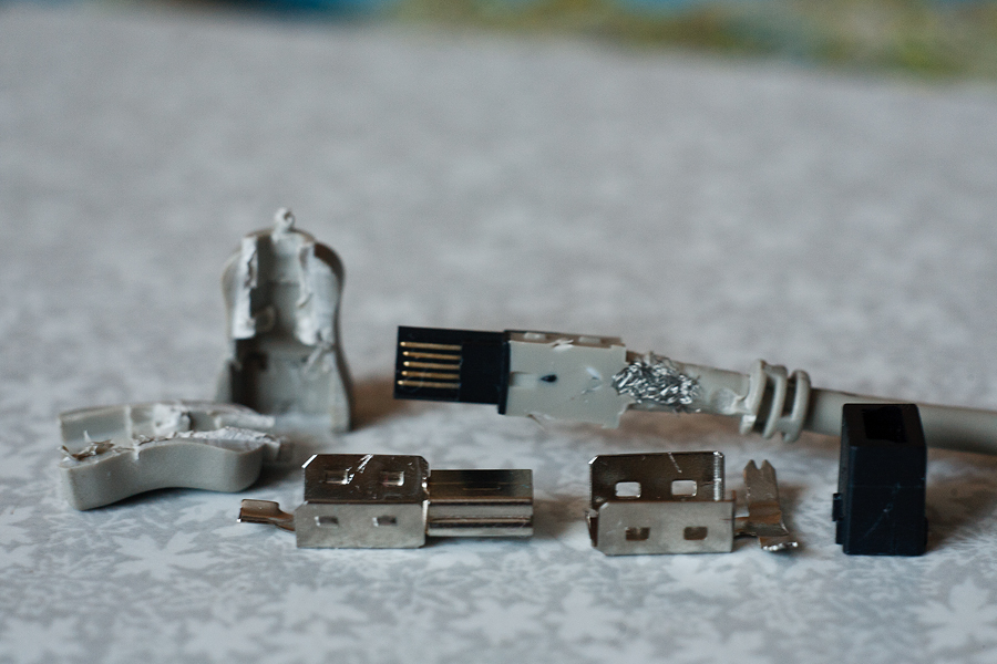
We take a regular mini-USB cable, carefully open its connector with a clerical knife. As a result, we get the following set of young technicians:
003.
Next, we need to connect the 4th and 5th pins of the plug. This can be done, for example, by carefully peeling off the sealing plastic from the back of the connector. But here two unpleasant surprises await. Firstly, it turns out to be not so easy to do without damaging anything, because the contact group is poured into conscience - you dig the hell out. The second "surprise" is the short contact of the 4th contact (forgive my pun!), Which makes it extremely inconvenient to solder something to it:
004.
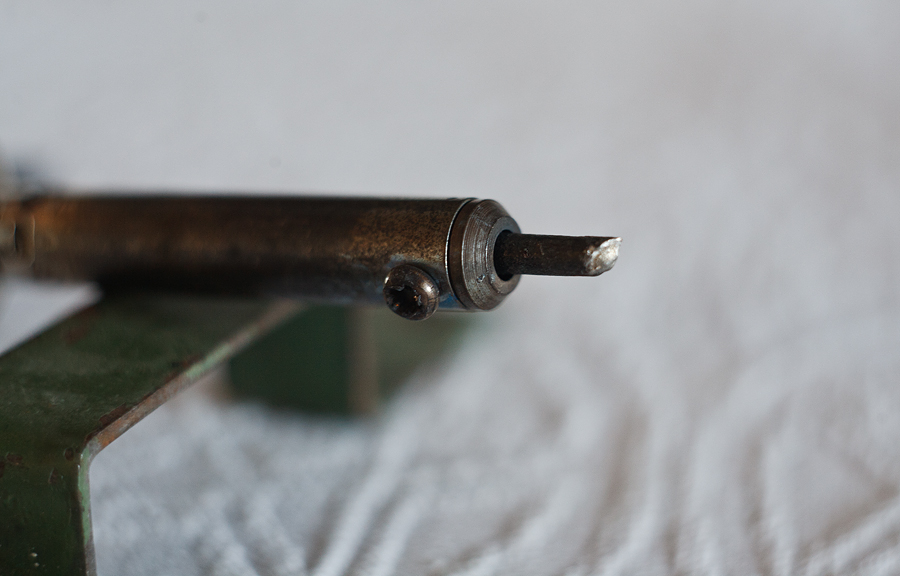
Honestly ruining the first cable, I take on the second one, but I am doing it a little differently. Having opened and disassembled the mini-USB connector, from the back of the contact pad, using the same clerical knife, I neatly scrape off the plastic in the area of the 4th and 5th contacts right down to the contacts themselves:
005.
Now we take a soldering iron and put a neat jumper between these two contacts with tin.
006.
The only thing you need to watch out for here is to keep the contact pad as flat as possible, and both from this side - since in this case our connector may simply not fit back into its metal case, and from the opposite (that is, actually from the side of the contacts) - since the unevenness there can lead to the bend of the contact group of the tablet socket, and this is already fraught. Having made a jumper, you need to take care to avoid short-circuiting the freshly soldered contacts with the connector body. To do this, I used such an indispensable tool as Poxipol.
007.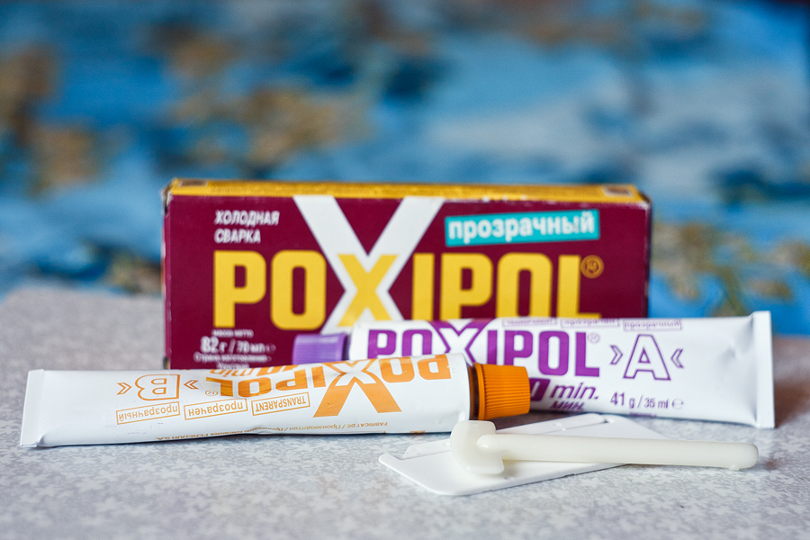
Please note that only TRANSPARENT Poxipol has electrical insulation. The metal Poxipol has quite conductive characteristics and, of course, cannot be used in this case.
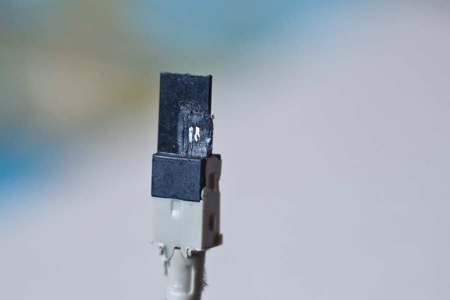
After the Poxipol has hardened, the excess can be cleaned off with a knife and the USB connector reassembled:
008.
In principle, it would be nice to fill it with Poxipol from above, but I recommend doing this after the cable has been tested for operability.
And cut off the USB-female connector from it with a piece of wire:
010.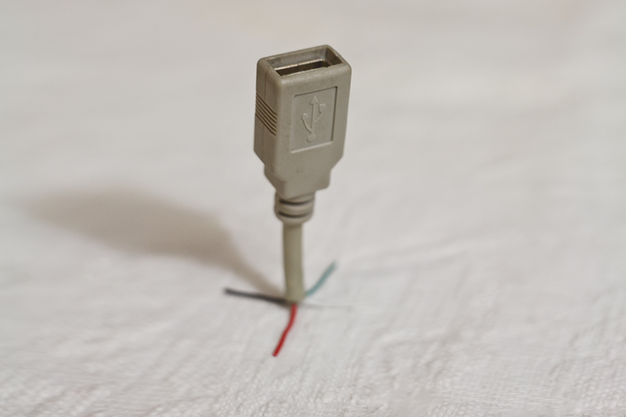
Now we only need to connect the two received cables (one with the mini-USB connector, the other with the USB-female connector) between each other.
First, we "dress" one of the wires with heat shrinkage:
011.
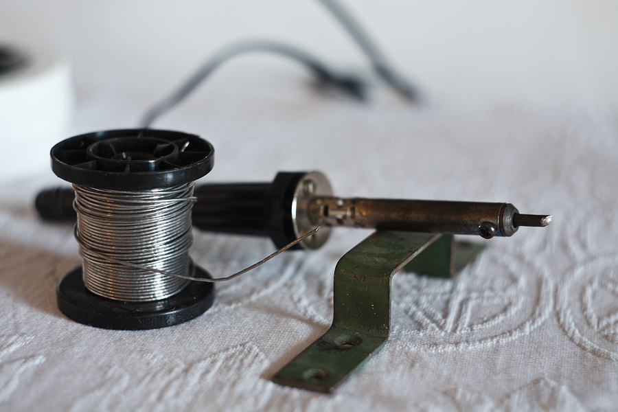
Take the soldering iron again:
012.
And carefully solder (from the word "solder" and not "solder"!) The wires in the cables.
013.![]()
To isolate the wires from each other, I used the same Poxipol. And when he froze, he put it on top together with heat shrink:
014.
As a result, we got such a cable.